pictures of the setup. Top row: The hypothosized hyperbolic camera, and the calibration
structure, a cylinder with known pattern. Bottom, the calibration photo used (original size:
1920x2560).
Inspired by "Calibration of a fish eye lens with field of view larger
than 180", CVWW 2002
Hynek Bakstein and Tomas Pajdla

pictures of the setup. Top row: The hypothosized hyperbolic camera,
and the calibration
structure, a cylinder with known pattern. Bottom, the calibration
photo used (original size:
1920x2560).
In this project, I designed a model to determine
the parameters of a 360 degree view
camera attachment. I will begin by presenting the basic algorithm
for optimization (due
to the Bakstein paper mentioned above). Then I will present
my contribution, which
is a different non-linearity in the reprojection step. Results
will then be presented.
The Setup.
The setup is as follows. In order to calibrate
a camera with an image, we must know
the 3D structure of the scene imaged. So we build a case where
we know points in
3 space and we know the corresponding imaged points on the calibration
image. I built
a hollow cylinder with a measured grating pattern on the inside.
Measuring the radius
of the cylinder, I then calculated the 3D coordinates of the points,
relative to the point
along the cylinder axis where I thought the center of projection
of the camera was. The
origin of the 3D coordinate space was chosen in order to have an
easier initialization (a
good initialization is necessary for most objective functions).
A model is then used, with some number of parameters,
to project (with the model) the
known 3D points. The projected points should closely match
the points we've identified
in the image, if our model and parameters are correct, as well as
up to inaccuracies in
our identified points (both in 2D and 3D). The Levenberg-Marquardt
algorithm is used
for choosing the optimal parameters for the model, in terms of minimizing
the error
associated with a projection, where the error is simply the sum
of the pixel differences
between the projected and calibrated points (the ones the user defines
to be the images
of the 3D points).
The Model.
The actual projection model I used is defined
here. We begin projection by
reorienting the the world coordinates into the camera coordinate
system, via a rotation
and translation,
X' = R*X + T
where R and T have 3 degrees of freedom each. The X' point
is then non-linearly
projected via hyperbola (described below) to a new point in 3D in
the camera coordinate
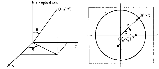
system. This point has the relation to the camera shown here.

Computing the coordinates (x',y',z'), we can derive theta.
We then use a stereographic
projection r = k*tan(theta/2) to get the radius of the point (distance
to the image point
that is on the optical axis). The phi in the image plane is
also computed from (x',y',z'),
and (u',v',1) in orthogonal image coordinates is then determined.
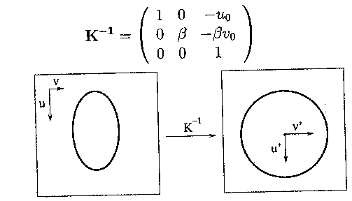
Finally, this image
point is mutliplied by an intrinsics matrix K, with skew assumed
zero.

As can be seen above, u_0 and v_0 are the optical axis point, and
beta is a scalar
measuring the squareness of the pixels. The final reprojected
image points are then
given by K*(u',v',1).
The hyperbolic projection in the middle of all
of this is simplified by the assumption
that the shape of the mirror is rotationally invariant. With
this assumption, the
reflection off of the mirror can be computed in the plane containing
the optical axis
and the point, for every point indepedently. Think of the
coordinate X' above,
immediately after the rotation and translation. Consider the
interaction in the plane
where the optical axis is the y coordinate, and the x is given by
the point's distance
to the optical axis, sqrt(x^2 + y^2).

Cylindrically then, the coord of the point is
(sqrt(sum([x y].^2)), z) = (Q,z). The camera is at
(0,0) and the focus of the hyperbola (for which the
camera is not the focus) is at (0,2c). The equation
then that solves for being on the hyperbola
subject to being on the line between (0,2c) and the
point in space is:
hyperbola params: a, c.
on pt = (0,2c) + t*(Q, z - 2c) t in [0,1] and
dist((0,0),pt) - dist((0,2c),pt) == 2a
solve for t and get perhaps two solutions. The one
I've found to always be on the correct hyperbola is
(-a^2+c^2)*(-2c^2+cz+ a*sqrt(4c^2+Q^2-4cz+z^2))
t = --------------------------------------------------------------------
-c^2*(-2c+z)^2 + a^2*(4c^2+Q^2-4cz+z^2)
Thusly, t is computed and the point in the plane that is actually
viewed (namely,
(0,2c) + t*(Q, z - 2c)) is determined. Theta is computed and
the projection
proceeds as specified above.
Some quick parameter counting before we move to
results. There are 6
parameters in the initial affinity and 3 in the K matrix.
The c and a variables
determine the spread of the hyperbola, and the k scalar used in
stereographic
projection defines the number of pixels per tangent unit (whatever
those are).
The total is then 12.
The Results.
There were 50 calibration points that I selected
in the image. The parameters
found were in the best case (the initial values are in the code):
x,y,z - rotations (in radians): 0.015273 -0.014428 -0.090647
x,y,z - translations (in .5 inch units): 0.167028 0.325886
-0.422814
u_0, v_0 (in pixels), beta: 961.58 1305.84 1.008926
c, a (in .5 inch units), k: 3.97223 4.32154 6500.14
Obviously, the rotation and translation are specific to this image
and so are
probably not applicable to the mechanism--though one never knows
where
intuitively the optimization will go in calibrating with a complicated
objective
space (some of the slack in a less-sensitive variable may be hidden
in another,
more sensitive one).
figure showing the errors on the image (left), and a graph of the pixel
error verses point
number. Notice that the error does not show systematic dependence.
The errors on
the left have been multiplied by 5, for better visibility. The
median error is 9.4 pixels.
To get the c, a and k specified above, I reoptimized
with respect to k, then c
and a. The non-linear optimization would not move the variables
much as long
as they were within a reasonable range. This led me to believe
the objective
function is bumpy. So I wrote the Optimize_* code (see top)
to test a large
range of initial values and choose the one with the best sum-of-square
distances
of the reprojection error. The non-linear optimization of
the best initial value was
then the final answer. This gave some improvement to the errors.
Also, running
the steps again (k with the best new c and a) did not improve things
(more
justification for a flat bumpy objective space).
I feel the majority of errors can be attributed
to my selection of points.
First, the points in three space may not be very accurately known.
They were
all selected to be on circular cuts through the cylinder, but there
may be slight
variations that through the high-resolution (and somewhat blurred)
photo
(1920x2560), and after hyperbolic reflection (and with the optical
axis perhaps
a bit off center), become a many-pixel difference from circular
in the image. So
I end up with a calibration where the declared 3D points would lead
to concentric
circles, but their images (and certainly my point selection) weren't
such circles.

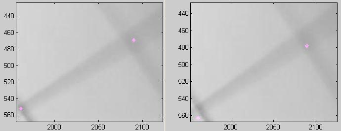
figure, two example errors. On the left is my hand selection,
and on the right is the best fit
model. One could argue that my point selection is wrong by at
least half the error in the best
reprojection. At such blur levels, I feel this is a better measure
than pixel distances (of
course, anyone with bad pixel differences says that).
Another assumption made, that I feel was reasonable,
was that the center of
projection of the camera was at a focus of the hyperbola (this is
implicit in
having the camera at (0,0) and the focus of the other half-hyperbola
at (0,2c)).
A final attempt at a slightly better error was
to take the optimum found using
all the points, and use those points that were inliers and start
over. Of course,
this should converge to the same solution, and it did, with slightly
lower error.
Ideally, there should be more calibration points.
Then one could optimize over
the hand placement while purging outliers. Overall however, I feel
the results are
decent and the model of the 360 camera setup is reasonable.