Programming Assignment
3: A LightField Viewer
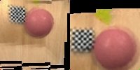
Figures: On the left, two separate renderings of a scene (objects in
a box).
On the right, the same view, with the rendering plane closer verses
farther
away. Notice the checkered cube (yes, it's a cube) and how it's
focus
improves with the movement of the rendering plane.
comp238_assn3.cpp
comp238_assn3_2.cpp
I started out by implementing an infinite
plane model, but then
saw that it was pretty easy to alter my code for an every-camera-
ponted at the center model. My basic recognition
is that anything
less than the best in lightfield rendering is pretty
bad. In the
following, I'll discuss the two variations on my renderer,
problems
faced and so on. The jist is that it runs very
slowly (one frame
per second or so) seems to do the right things.
First, the common characteristics.
There is a plane of cameras
spaced along the positive xy plane as they were in capture.
The
rendering plane is though to be (and move) perpendicular
to the
negative z axis, with the rendering distance then being
the z coord
on that plane (sometimes called the scene plane).
The up
direction is along the positive y axis. The view
can be changed by
pan/tilt, translation, and change of focal length.
Change by
translation is simply modifying the center of projection.
Pan is the
two dimensional rotation of the x and z coordinates (the
axis of
rotation being the positive y axis), and tilt is by a
spherical linear
interpolation from the current direction of view towards
(or away
from) the positive y axis.
Every time a frame is rendered, the
projection matrix is
recalculated. For each ray extending from the eye
through a
pixel, a twice-bilinearly interpolated color is retrieved.
The ray's
intersection with the scene (far) plane is calculated
and this point
is projected back onto the images of the four cameras
closest to
the ray's intersection with the sea of cameras (near
plane). Since
a given such intersection is unlikely to be on integer
pixel coords,
the color returned for each image is bilinearly interpolated.
Then,
the four colors are themselves binlinearly interpolated,
factored by
the ray's distance to the four cameras on the near plane.
With this framework, one can see that
it doesn't matter how
the cameras were directed in capture, as long as their
directions
of view and focal length are known (the back projection
from the
scene plane uses the inverse of the projection matrix
determined
by this direction and scaler).
The first implementation is with an
infinite plane. All cameras
are pointed in the same direction. This makes it
easier in the
color computation above because only one projection matrix
is
needed for the back projection, with changing center
of projection
(my projection matrix is from the one true way, a 3x3
projection
of pixel coordinates [i j 1] to a 3d direction vector,
without a fixed
origin).
This implementation has several lackings.
First the parallax is
limited without a large field of view for the capture
cameras. But
the obvious fix to this leads to excessive perspective
distortion.
There are also undesirable effects that make sense intuitively
but
make at least this lightfield renderer not so good.
For example,
as the eye moves away from the sea of cameras, the rays
tend to
approach parallel, decreasing the field of view of the
visible scene,
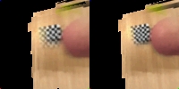
but also distorting the part seen:
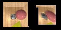
Figure: Image as seen from the near
plane, verses back from the plane.
But overall, parallel planes implementation works.
As implied above, the only real difference
between the infinite
plane verses by other model is that in the new model,
each
camera is represented with a different projection matrix.
The
second model I implemented is where every camera points
to
center of the scene plane. This helped create some
neater
looking views than the simpler camera setup did (top),
but the
principle is exactly the same: to render an image, project
every
pixel onto the scene plane, and project back onto the
image
plane, then come up with a reasonable value for that
ray based
on nearby rays from the camera plane that intersect
the same
point on the scene plane.
Given the first implementation, the
second took very little
time. I only compute a given projection once, when
reading in
the image files. The row and column, along with
the spacing
between cameras, provides the direction of the camera
for a
particular image, and the focal length is given.
Speed is the main attribute that can
be improved in both
implementations. The programs run at about a frame
per
second, which is too slow for image based rendering.
The
program is basically a ray tracer that looks up color
values,
and thus doesn't take much advantage of coherence (as
along
a scanline). A test I ran, where I linearly interpolate
the camera
plane intersections along a scanline did little to improve
the
performance. I think the greatest gains may come
from not
having so many function calls per pixel. On the
image being
generated, one could determine the boundaries of regions
over
which the same images are being interpolated. Then
one could
load those images ensemble and reduce the function calls.
Further, perhaps the interpolation between images can
be
iterative along a line in one of these regions.
I like the idea of such a system, but
it has very quickly
growing complexity for decent quality. You have
n squared
on each particular image's quality improving. At
least n squared
for number of images (as on a plane). But you're
always stuck
to around views that you have pictures from, and it's
only good
quality at the exact sample points. So there's
very restricted
movement and nothing like a flythrough and little to
no
geometry. For me, this leads to very limited realism.
If you
could make (as in capture) a lightfield quickly and store
it very
efficiently, I can see something like email attachment
lightfields
to give people somewhat more presence than a picture
would.
Anyway, neat stuff.