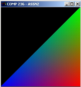
I implemented a triangle scan conversion routine and Z-buffer
hidden surface algorithm. I started
with Bishop's skeleton glut code and used the frame buffer
from that, with an additional array pz
(pixel z) for the z buffer.
My approach was to use a bounding box. Upon entry
into the function, a bounding box is found.
A line has the form y - kx + (k*x1 - y1) = 0, where x1
and y1 are coordinates of a point on the
line. The last term is a constant, so I calculate
k and the last term b for the three edges. Then, for
each scanline in the box, several things happen:
Vectors of x y and z are calculated
for interpolation later on.
I initialize the edge equation above
(left hand side), and it evaluates to positive or negative
based on which
side of the edge the point being evaluated is on. I found that if
the traversal
of the edge
decreases in x, then by negating the function and subsequent iterations,
I get the
property that
if a point is within the triangle, then the three edge functions have the
same sign
at that point.
I find the z and x being interpolated
along on this row. I do this by picking the two edges such
that the row
is in their range. Then I interpolate along those edges to get two
z's and two x's.
Then, for each pixel:
Increment the edge functions accordingly.
Check if any of the edge functions
evaluated to zero. If so, set them to be one of the non-zero
evaluations.
All three will never be zero.
Finally, if the three evaluations have the same sign,
compare the interpolated z to the current z in
the pz array. If the triangle is to be drawn at
this pixel, interpolate it's color and update the frame
buffer.
Optimizing?
My code was written with large triangles in mind.
My edge equation incrementing and prep-
rocessing for each row only matter if there are a good
number of pixels on the row to check. In
order to optimize for much smaller triangles, I would
probably cut out most of the code. I would
start by again finding the bounding box. If we're
only evaluating at pixel centers, I may then check
first to see if the max z of the triangle is greater
than any z currently in the box of pixels. For each
pixel that looks like it could get written to, I would
then do the edge equation evaluations and if
necessary the interpolations for the pixel. The
comparison with all the pixels in the bounding box
is not efficient for large triangles. But if a
triangle is only a few pixels or less, we could probably
save some time by not having to calculate and evaluate
edge equations. However, even in the
large triangle case, it could be helpful to delay the
edge equation incrementing until we find a good
z, but then we would have to keep track of how much to
increment by once we got to one. (It's
just that in my code, the cases being accounted for regarding
the different traversals of edges
looks like a lot of comparisons per pixel. To be
able to stop short of those could be nice, part-
icularly if there are a lot of overlapping triangles
in the image).
The only coherence I take advantage of (I think) is the
incrementing rather than reevaluating the
edge formulas. I guess by coding so straight-forwardly,
I've made an algorithm that would be
easier to implement on hardware than others that optimize
more for the different cases.
Model for Time Behavior
My model was same one discussed in class, namely:
Ttotal = Tsetup + Nlines * Tline + Npixels * Tpixel
I ran the program on hundreds of randomly generated triangles,
and output a file containing
basically a hundreds by 3 matrix. The knowns are
Ttotal, Nlines, and Npixels. To solve the
system I used the method we dicussed in class for non-square
matricies:
Ax = B
A'Ax = A'B
x = inv(A'A)A'B
I took my space delimited text file and imported into
matlab to do the math, basically repeating
the above sequence:
>> A = output(1:500,2:3);
>> A(1:500,3) = ones(500,1);
>> B = output(1:500,1);
>> AT = A';
>> C = AT*A;
>> D = AT*B;
>> x = inv(C)*D
x =
1.0e-003 *
0.0970
0.0018
-0.8924
>> for i = 1:500
approx_r(i) = output(i,2)*x(1) + output(i,3)*x(2) + x(3);
end
>> i = 1:500;
>> resi = output(1:500,1) - approx_r(1,1:500)';
>> plot(i,resi);
(see below for plot)
>> r = sum(resi.*resi)
r =
0.0968
>> cond(A)
ans =
1.4930e+004
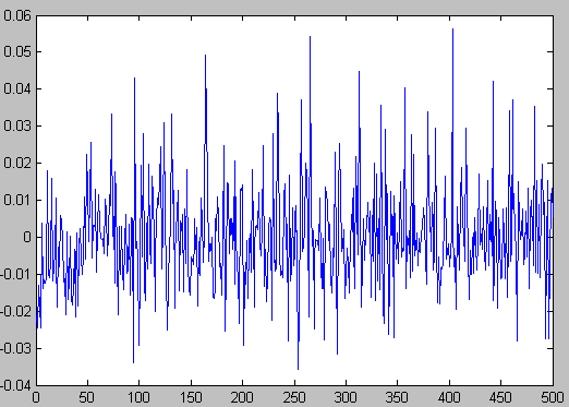
The residue is nice and small, but the variables got solved so that the equation is:
Ttotal = (-8.92 E -4) + (9.7 E -5)*Nlines + (1.77 E -6)*Npixels
Why there is a negative Tsetup I don't know. Maybe the fact that
the condition number
(sensitivity to error) of the system matrix A is about 15K! And when
we multiply it by
it's transpose, we get like the square of the sensitivity. But
the results of the solution are
good (averaging about 6% difference between the fitting curve and the
data). So maybe
the model is off a bit. It seems intuitive though. We would
get more accuracy on the
Tline and Tpixel if we estimated the Tsetup. I could compute
that along with Nlines and
Npixels and Ttotal for a large number of triangles, and find it's average
and distribution
to get some sort of reasonable constant Tsetup. However, here's
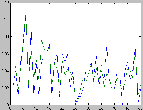
a fit on 50 triangles for
example (the projected total time in green, verses the actual total
time in blue. The results
are pretty good:
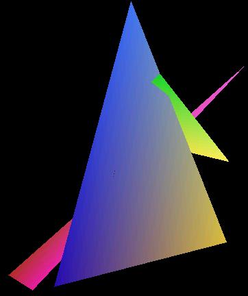
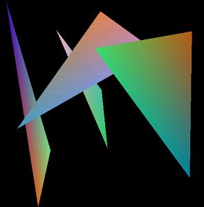
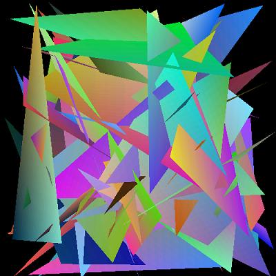
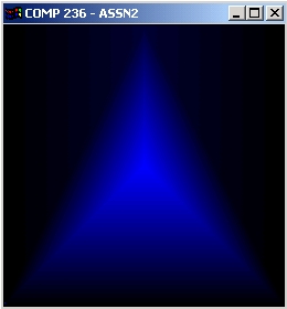
Some Examples: